A commercial battery energy storage system (BESS) can be electrically complete, energized and free of active faults and still refuse to deliver the power an operator expects. For example, a 500-kW system stops at 350 kW despite the inverter nameplate saying 500 kW. Nothing on site has failed.
That situation is getting more common as storage attaches to commercial solar, and it is harder to diagnose than a string voltage problem, because the limit rarely sits in the box the technician is standing next to. A BESS is operated by several control systems holding different authority, and the constraint that binds at any moment can come from any of them.
Three boxes, three different decisions
The battery management system (BMS), power conversion system (PCS) and energy management system (EMS) are usually described together as an integrated package. They do not have the same authority.

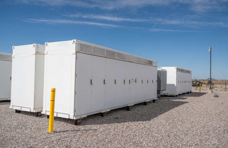
Battery energy storage systems. Credit: EDP Renewables North America
The BMS sits closest to the battery. It monitors cell and rack voltage, current and temperature, and uses those measurements to estimate conditions such as state of charge (SOC). Its more consequential role is setting the battery’s present operating envelope. Depending on temperature, state of charge and cell condition, the BMS may reduce how much charge or discharge is currently allowed, or initiate protective action. IEEE 2686-2024 treats the BMS as a functionally distinct part of the BESS, containing the functions needed to protect battery safety and longevity, and it explicitly leaves dispatch of power and energy to and from the grid outside its scope.
The PCS converts power between the battery’s DC system and the site’s AC system. It executes real and reactive power functions within its own electrical ratings and within the limits the battery controls hand it. (Storage submittals also use “PCS” for a power control system, an NEC term for a listed device that limits current and loading on busbars so existing service equipment can remain in place. It converts nothing. Confirm which one a drawing means before assuming which device is holding a limit.) Sandia National Laboratories describes the arrangement as operating data moving up from the equipment while commands move down toward the PCS, with the PCS interfacing with the BMS so that battery limits are not violated while a commanded power is delivered.
The EMS or site controller sits above both. It decides what the project wants: charge from surplus solar, discharge into a demand peak, hold an export limit, follow a schedule. It requests power. A request is not a guarantee the battery can supply it.
When the numbers disagree
Take a 500-kW PCS. The site’s operating objective calls for 500 kW of discharge. The BMS, evaluating present battery conditions, is reporting a discharge limit of 350 kW. The system delivers 350 kW. No fault is logged, because nothing has failed. The nameplate describes what the inverter can convert, not what the battery will presently allow.
Now add a utility requirement holding export at the point of interconnection (POI) to 250 kW. That is a third boundary, and it constrains something different. It limits what crosses the POI, not what the battery produces. Ignoring conversion losses and any concurrent PV production, a 350-kW discharge against a 100-kW building load puts roughly 250 kW across the POI.
Three limits, three different boundaries. Battery limits constrain what moves through the battery. PCS ratings constrain conversion. An export limit constrains what crosses the meter. Troubleshooting from a single setpoint will mislead you.
That makes measurement location a field problem rather than a design abstraction. An export controller cannot regulate the POI if its CTs are on the wrong feeder, reversed, scaled incorrectly or reporting from the wrong side of a boundary. It is also worth remembering that a communications link showing as online does not prove the values crossing it are being interpreted correctly. Registers carry units and scaling, and a value read as watts when it was sent as kilowatts produces a system that appears to be talking and behaving strangely.
Stopping is not one thing
“Shutdown” describes several unrelated events.
An abnormal battery condition may cause the BMS to restrict operation or initiate protective isolation, depending on the manufacturer’s control architecture. Dispatch commands do not override those limits.
An operator or EMS stop-command brings power to zero or places the PCS in standby. Nothing is wrong.

An energy storage project in Vermont. Credit: Encore Renewable Energy
A grid disturbance is different again. Response to abnormal grid conditions and unintentional islanding belongs to the PCS and the interconnection protection, not to the BMS. IEEE 1547 establishes those requirements, IEEE 1547.9 applies them to energy storage and IEEE 1547.1 provides the test procedures. Also important to note is that not every disturbance produces a trip. Ride-through is a required capability, and the interconnection authority specifies or approves project settings within the equipment’s supported range. Those settings should not be assumed from factory defaults.
Communications loss is a fourth case. If the controller loses its link to the PCS or BMS, does the system hold its last setpoint, ramp to zero, or enter another defined state? There is no universal answer. It follows from the listed system, the manufacturer’s documentation and the project controls design, and it should be tested rather than assumed.
What to verify before turnover
An ESS listed to UL 9540 is evaluated with its controls and inter-device communication in scope, which means those interfaces are part of what was approved. Proving they work is field scope.
Contractors do not need to reverse-engineer BMS software. They need to establish that each boundary behaves as designed and know where the answer comes from when it does not. Drawing on recurring control and commissioning issues on commercial and industrial solar-plus-storage projects, I developed the Control Boundary Checkout to verify the interfaces between battery, conversion, dispatch and interconnection controls.
| Boundary | What the field test establishes | Who supplies the documented answer |
| Battery limits: BMS to PCS and controller | Present charge and discharge limits, SOC, status and alarms reach the PCS and the controller with correct scaling and units | Battery or ESS manufacturer |
| Dispatch commands: EMS or site controller to PCS | Controller commands produce the expected PCS response within the battery’s present operating limits and any applicable system limit | Controls integrator or EMS supplier |
| Export measurement: POI metering to controller | Metering and CTs represent the intended electrical boundary with correct polarity and scaling, and the system reduces output as the export limit is approached | Design engineer, field-verified by the installer |
| Stop conditions | The system reaches its documented state on operator stop, on a grid event, and on an introduced communications failure | Manufacturer or controls integrator for equipment and communications behavior; interconnection requirements for grid-event response |
| Settings access | Required limits and modes are configured and locked before turnover, and the process for later changes is documented | Manufacturer or controls integrator or owner, under restricted-access requirements |
The last row matters after the crew leaves. Export limits, operating modes and grid settings are commissioned values, and access to them is typically restricted to qualified personnel. Someone changing an export setpoint months later will not break anything electrically. The system will simply stop operating the way it was approved to operate.
The takeaway
A BESS is not controlled by one box. It is a chain of systems holding different authority, and a system that will not reach 500 kW is usually a system doing exactly what it was told by whichever layer has the tightest constraint at that moment. The same checkout applies wherever a storage system is operated by separate battery, conversion and dispatch controls. Testing those boundaries before turnover turns a confusing callback into a question with an address.
Archit Patnaik, PE, PMP, NABCEP PVIP, is a senior project manager at Pure Power Engineering, where he leads electrical engineering for commercial and industrial solar PV and battery energy storage projects.